Or: Creating an audio-signal with an Arduino, feeding it into a mixing desk, altering the frequencies via the mixer’s eq and analyzing the processed audio with another Arduino which then turns it into a MIDI-signal. Yes, that is Digital-to-Analog-to-Digital-to-Analog-to-Digital-conversion. Phew!
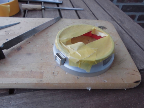
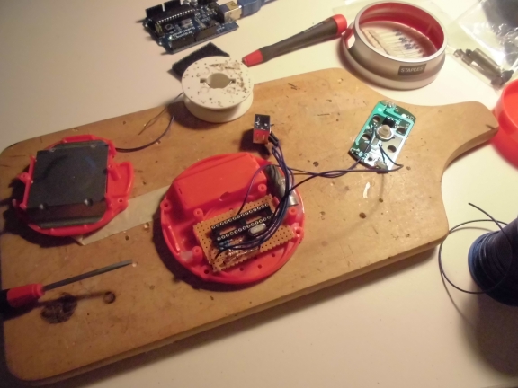
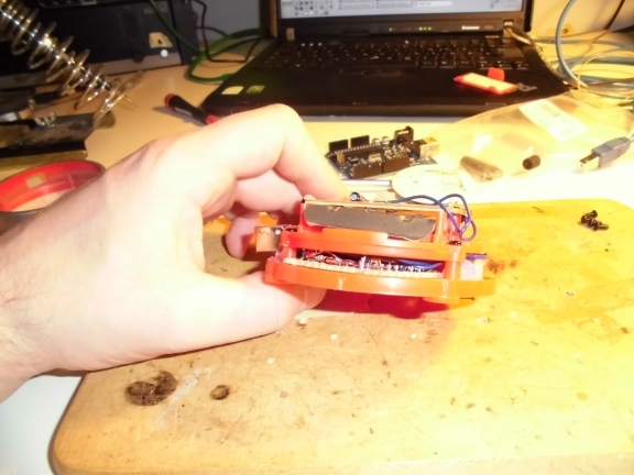
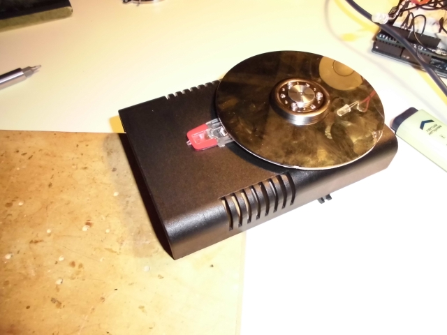
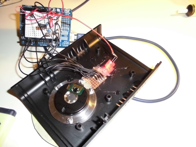
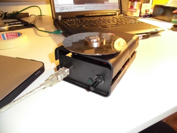
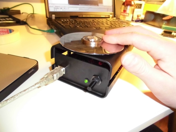
Here’s a picture of the setup:
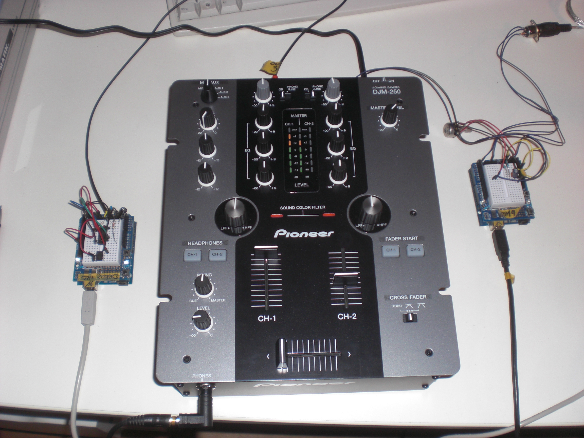
On the left side there is a circuit consisting of an Arduino and an Attiny85. The Arduino creates a low-frequency ( ‘bass’ ) sine-shaped tone which perfectly sits in the frequency range of the mixer’s bass-EQ. I did some testing here to find the perfect frequency. Testing means: Using Ableton Live to create a white noise, feed this into the mixer, feed the mixer’s output back into Ableton and use the Spectrum-tool to see which frequency gets most influenced by the bass-EQ (C2, that is).
Creating a somewhat true sine needs some effort since the Arduino’s analog outputs only do PWM which isn’t very useful when talking about low-frequency audio signals. PWM basically creates a square-wave signal with a certain pulse-pause relation. While this might be okay for dimming an LED, this becomes quite unusable when dealing with audio because you can simply hear that it’s no sine – the lower the frequency the more the signal turns into some sort of ‘click’-noise. No wonder, the bass-EQ doesn’t influence this to any convience.
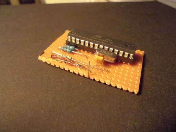
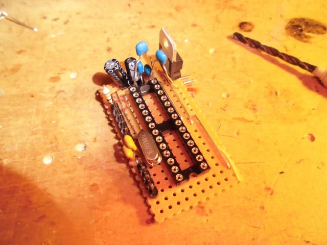
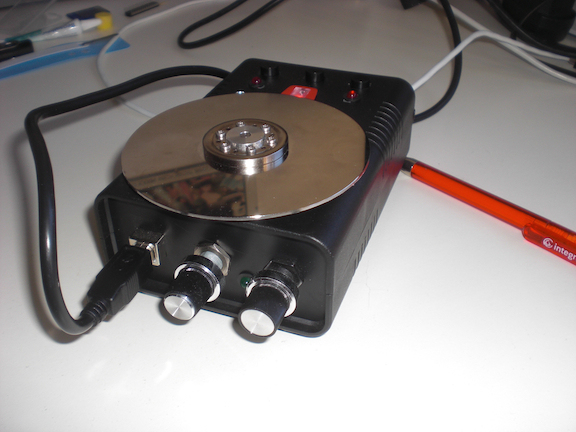
That’s why I used this solution to make the Arduino spit out something that’s a little more sinewave-like. I ommitted the circuit as you may see on the picture below. I didn’t have the necessary parts lying around and it worked nevertheless.
The Attiny85 is used to create the second tone. It’s a simple PWM signal at 480 Hz. This time the PWM-nature of the signal can be used for our benefits: A square-wave signal has a recognizable amount of harmonics. You don’t hear one but (at least) two tones. Perfect for us because the mixer I used perfectly influences (well … “perfectly” ) the signals with its mid- and hi-EQs.
The code for the Attiny85 looks like this:
void setup(){
pinMode(3, OUTPUT);
}
void loop(){
buzz(3,480,100);
}
void buzz(int targetPin, long frequency, long length) {
long delayValue = 1000000/frequency/2; // calculate the delay value between transitions
long numCycles = frequency * length/ 1000; // calculate the number of cycles for proper timing
for (long i=0; i < numCycles; i++){ // for the calculated length of time…
digitalWrite(targetPin,HIGH); // write the buzzer pin high to push out the diaphram
delayMicroseconds(delayValue); // wait for the calculated delay value
digitalWrite(targetPin,LOW); // write the buzzer pin low to pull back the diaphram
delayMicroseconds(delayValue); // wait again or the calculated delay value
}
}
I guess I found it over here and adapted it to my needs.
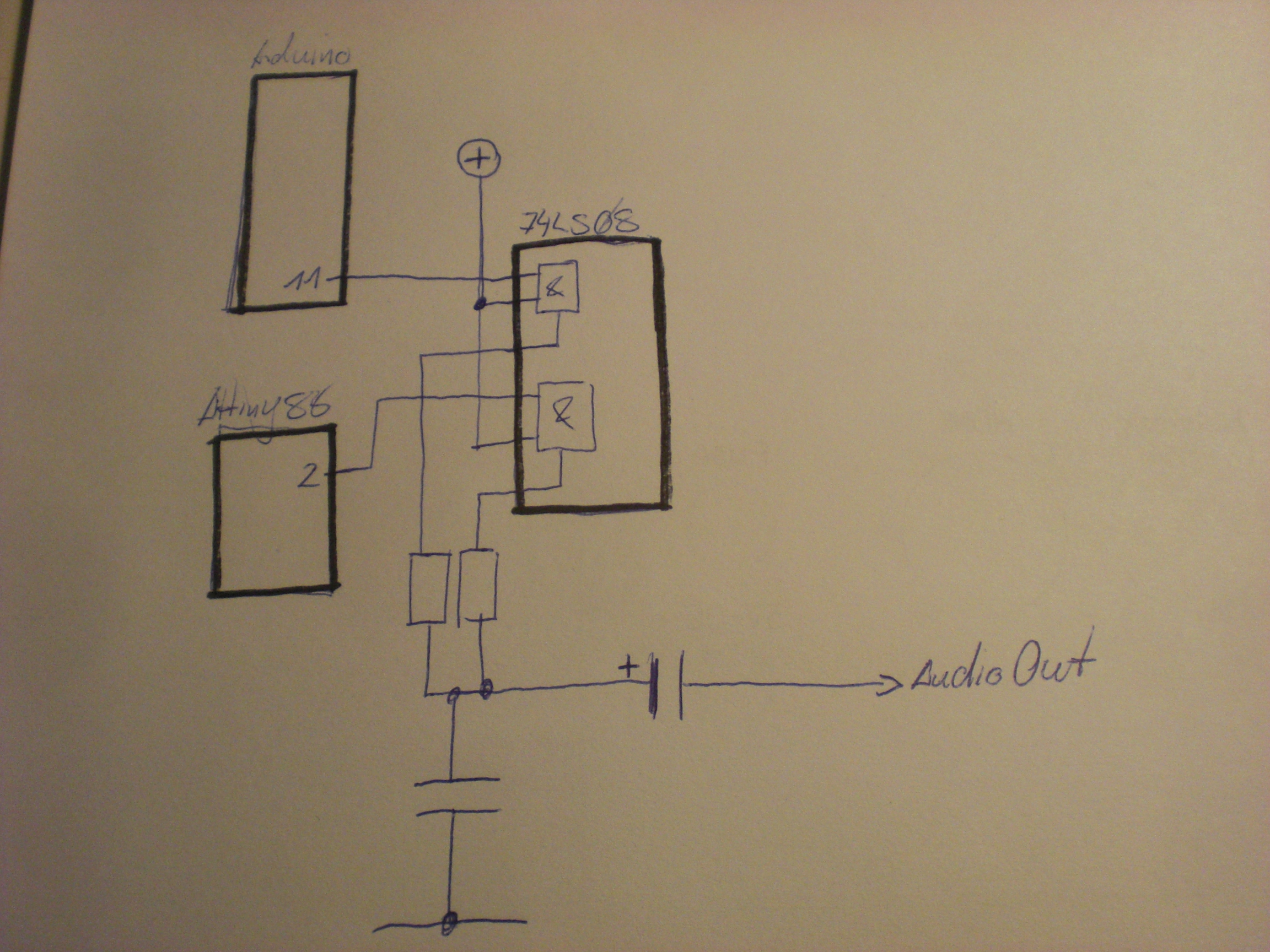
the two microcontroller’s output signals are fed into a 7408 (Quad AND) and then sent out into the analog world by a circuit I found over at the MunichMakerLab. This is my first audio-circuit with an Arduino. it’s probably spine-crawling for those who do this on a more professional base but I was getting the best results with this circuit.
[Edit] As someone pointed out in the comments section for this post on Hackaday this might read like I didn’t know at all what I am doing here or that it’s all just a big coincidence. This is not correct. The AND gate protects the audio sources from interfering with each other for a certain amount. I tested that, it simply sounds cleaner. At least I had a certain intention when I added the gates to the circuit (…not that I completely remember….). Looking at the circuit I am still wandering about _why_ but that’s one of the things that I file as ‘Audio things’ for now. [/Edit]
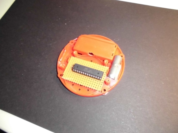
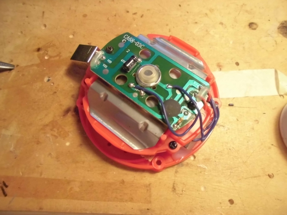
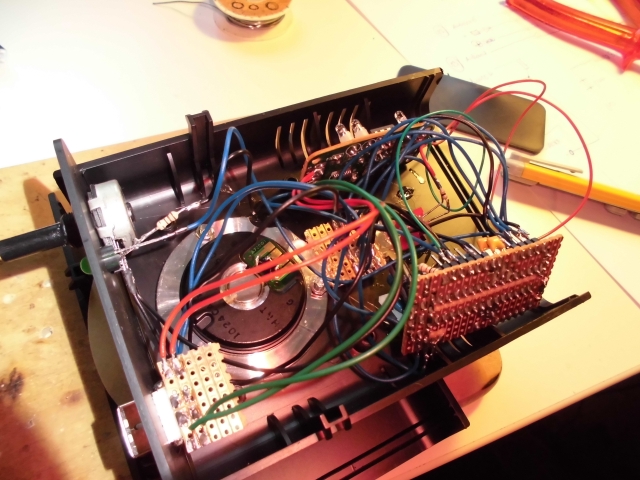
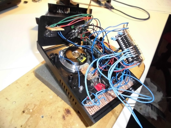
The signal is fed into the mixer and from the mixer sent to another Arduino which does the processing. the circuit looks like this:

To be honest: I cannot really remember where I got this circuit from. Somehow all the solutions I found while trying to find the circuit again look a little different. Again this might be spine.crawling for some of you but… it’s a fun project and it works. The code for the realtime audio-analysis is based on the FHT library by openmusiclabs and expands an example I found over at dontquityourdayjob.
/////////////////////////////////////////////////////////////////////
// Easy Customizations
/////////////////////////////////////////////////////////////////////
// Adjust the Treshold – what volume should make it light up?
#define THRESHOLD 40
// Attempt to ‘zero out’ noise when line in is ‘quiet’. You can change this to make some segments more sensitive.
int oct_bias[] = { 600, 600, 1, 100, 50, 50, 50, 50 };
// Divide Threshold by 2 for top octave? 1 – yes 2 – no. Makes highest frequency blink more.
#define TOP_OCTAVE_DIVIDE false
/////////////////////////////////////////////////////////////////////
// Hard Customizations – know what you are doing, please.
/////////////////////////////////////////////////////////////////////
// FHT defaults – don’t change without reading the Open Music Labs documentation at openmusiclabs.com
#define LOG_OUT 0 // use the log output function
#define FHT_N 256 // set to 256 point fht
#define OCTAVE 1
#define OCT_NORM 1
// Delay – defines how many cycles before the lights will update. OML’s algorithm at 256 samples (needed for our 8 octaves) takes
// 3.18 ms per cycle, so we essentially throw out 14 cycles (I used mechanical relays, you can lower this for solid state relays).
// 15 cycles = 47.7 ms update rate. Be careful here and don’t change it too quickly! I warned you!
#define DELAY 15
#include <FHT.h> // include the library
#include <MIDI.h>
void setup() {
Serial.begin(31250); // use the serial port
TIMSK0 = 0; // turn off timer0 for lower jitter
ADCSRA = 0xe5; // set the adc to free running mode
ADMUX = 0x40; // use adc0
DIDR0 = 0x01; // turn off the digital input for adc0
}
/**********************************************************************************
Loop – includes initialization function and the full loop
**********************************************************************************/
const int NUMREADINGS=10;
int readings[NUMREADINGS]; // the readings from the analog input
int index = 0; // the index of the current reading
int total = 0; // the running total
int average = 0;
int bassVal;
int midVal;
int hiVal;
int bassValOld;
int midValOld;
int hiValOld;
const int OUTTHRESHHOLD = 4;
void loop() {
// True full loop
int q = 0;
while(1) { // reduces jitter
cli(); // UDRE interrupt slows this way down on arduino1.0
for (int i = 0 ; i < FHT_N ; i++) { // save 256 samples
while(!(ADCSRA & 0x10)); // wait for adc to be ready
ADCSRA = 0xf5; // restart adc
byte m = ADCL; // fetch adc data
byte j = ADCH;
int k = (j << 8) | m; // form into an int
k -= 0x0200; // form into a signed int
k <<= 6; // form into a 16b signed int
fht_input[i] = k; // put real data into bins
}
fht_window(); // window the data for better frequency response
fht_reorder(); // reorder the data before doing the fht
fht_run(); // process the data in the fht
fht_mag_octave(); // take the output of the fht
sei();
if (q % DELAY == 0) {
//—-Smoothing
// subtract the last reading:
total= total – readings[index];
// read from the sensor:
readings[index] = (fht_oct_out[1] – oct_bias[1]);
// add the reading to the total:
total= total + readings[index];
// advance to the next position in the array:
index = index + 1;
// if we’re at the end of the array…
if (index >= NUMREADINGS)
// …wrap around to the beginning:
index = 0;
// calculate the average:
average = total / NUMREADINGS;
//—-
//Werte:
bassVal = average; // : Bass
midVal = fht_oct_out[4] – oct_bias[4]; // Mitte
hiVal = fht_oct_out[7] – oct_bias[7]; //Hochton
bassVal = map(bassVal, -450, -390, 0, 127);
midVal = map(midVal, 9, 107, 0, 127);
hiVal = map(hiVal, -34, 20, 0, 127);
if((bassVal > bassValOld+OUTTHRESHHOLD) || (bassVal < bassValOld-OUTTHRESHHOLD)){
if((bassVal>=0) && (bassVal<=127)){
Serial.write(0xb0);
Serial.write(0x01);
Serial.write(bassVal);
}
bassValOld = bassVal;
}
if((midVal > midValOld+OUTTHRESHHOLD) || (midVal < midValOld-OUTTHRESHHOLD)){
if((midVal>=0) && (midVal<=127)){
Serial.write(0xb0);
Serial.write(0x02);
Serial.write(midVal);
}
midValOld = midVal;
}
if((hiVal > hiValOld+OUTTHRESHHOLD) || (hiVal < hiValOld-OUTTHRESHHOLD)){
if((hiVal>=0) && (hiVal<=127)){
Serial.write(0xb0);
Serial.write(0x03);
Serial.write(hiVal);
}
hiValOld = hiVal;
}
}
++q;
}
}
The whole mechanism is not THAT precise but it gets the job done and it’s a fun thing to watch. The bass-frequency has to be smoothed-out quite a bit in order to make it all work. After spending a little more than a day with this some might ask “what for?”. I tell you what for: for the sake of finally doing it. I had this idea for over a year now and it was well worth trying.
The system is quite slow in its reaction (mainly caused by the necessary smoothing) and results are still a bit unpredictable but turning an audio-mixer into a midi-controller just by using hardware of ~10€ ain’t too bad, isn’t it?
[tube]https://www.youtube.com/watch?v=u5r6i65eHKk, 720, 540[/tube]