This is my attempt to build a Midi turntable (a.k.a. Jogwheel) from an old harddrive.
Some time ago I came across this (rather famous) article:
A hard drive hacked into a turntable
What they basically did here is to take an old harddrive and connect the motor via a set of op-amps to a microcontroller. When the platter is moved the motor (now actring as a generator) will produce signals that can be analysed by the µC and used for generating Midi out.
So far so excellent. But the deeper I got into the topic the more it became clear that this wasn’t the best solution for me since the article states that very small and slow platter-motion isn’t detected reliably.
That’s why I started building my own version of a harddisk turntable using the optical sensor of an old mouse.
Here we go, it all starts with an old harddisk
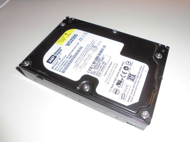
I have been dealing with computers for more than 20 years now but this is the only harddisk I had ever problems with. And this probably wasn’t caused by one of those “ooh my god…my harddisk suddenly crashed”-moments ismply but due to accidentally dropping it while moving to another flat.
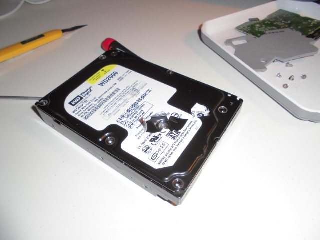
So – this is the first time ever that I’m taking apart a harddisk….
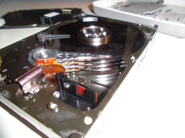
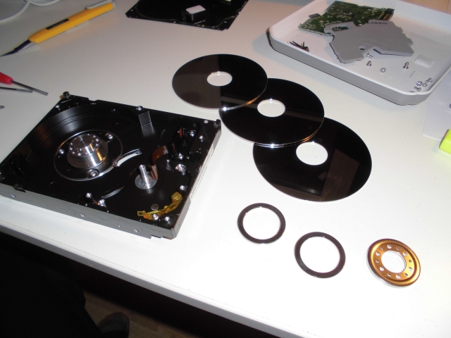
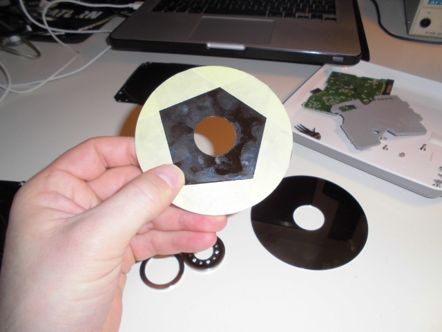
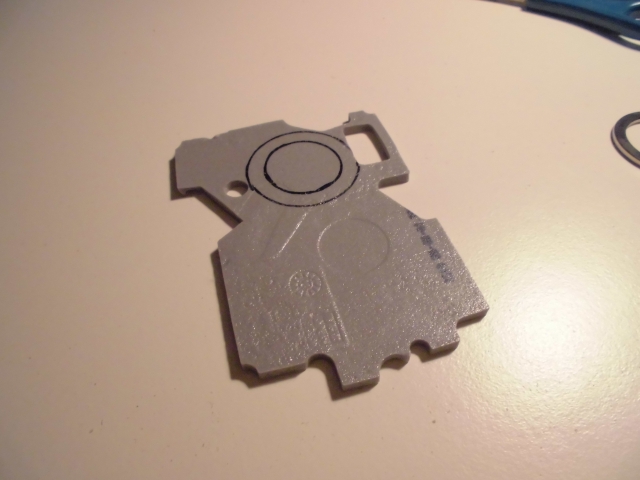
I figured out that I had to get rid of two platters because it would make the construction too heavy an dull-feeling.
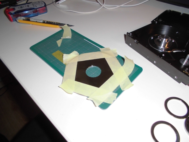
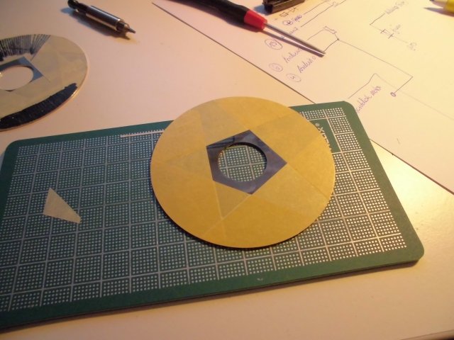
In order for the optical sensor to be able to detect the platter being moved I taped the edge of the platter to give it some structure.
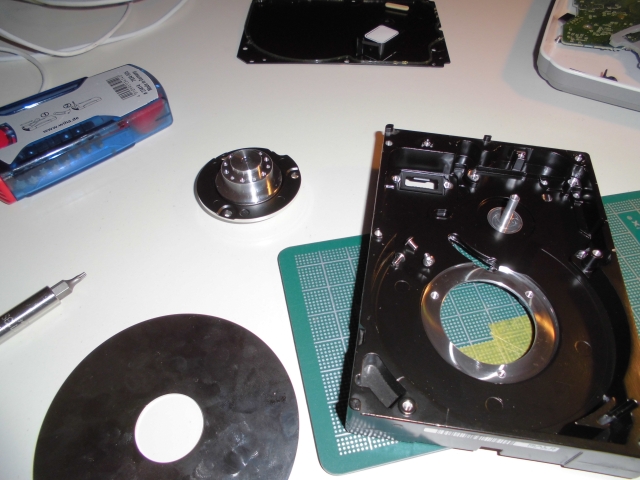
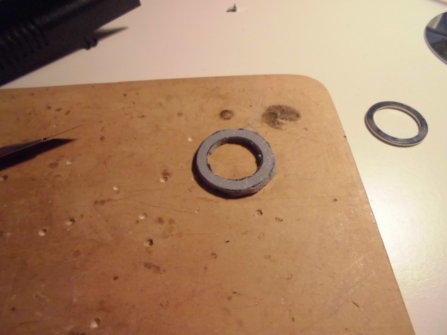
Fortunately the harddrive motor could completely be detached from the housing. This way I can use it in another case
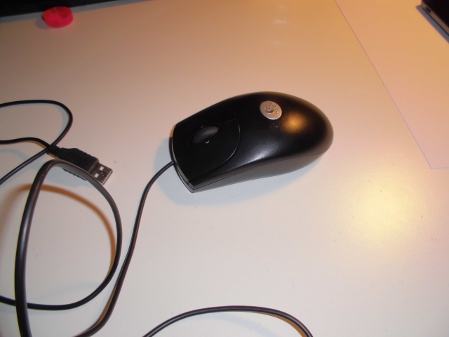
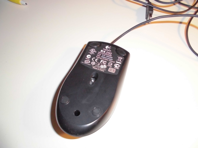
The mouse was a Logitech RX250 that I had lying around
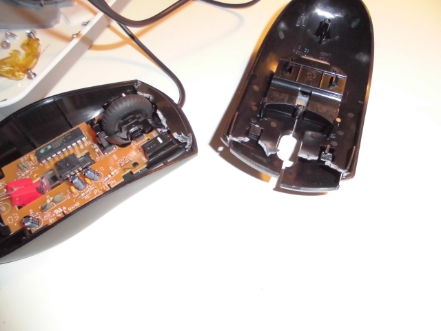
The sensor is of type A5020E. Fortunately I found an Arduino library for this device over here. It’s a little bit old and in order to make it work under Arduino 1.0.1 you have to exchange
#include “WConstants.h” against
#include “Arduino.h” in the .cpp file. That’s all.
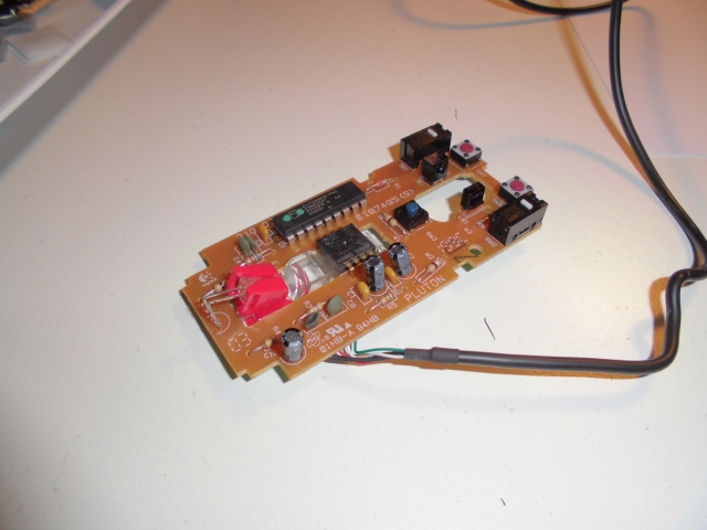
I simply desoldered the sensor and put it on a scrap piece of vector board. This will later be fixed by hotglue-influenced-technology =). the datasheet can be found here or here (if the original site will change or be offline).
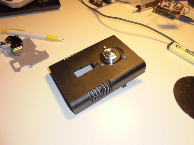
During the first attempts I found out that it’s a good idea to keep the clear piece of plastic together with the mouse’s original LED in order to have the right conditions for the optical sensor’s illumination. For that reason I cut an appropriate hole into the new case.
It is pretty save to say that I am by far one of the worst craftsmen around….
Because I left away two of the three harddisk’s platters I had some space that needed to be filled up. This piece of foam comes from inside the old harddisk
Some hotglue later
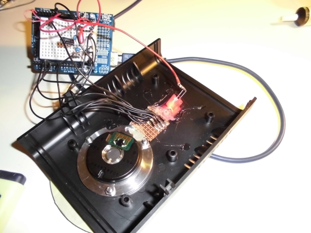
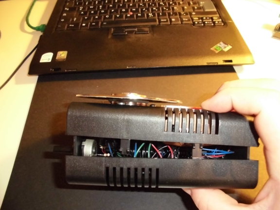
At the moment the circuit only exists on an Arduino breadboard. I will fix this later
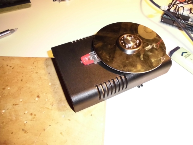
Proof of concept
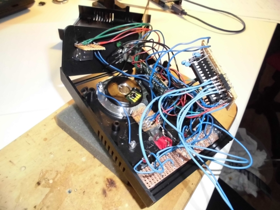
Normally I try to create all my circuits as clean as possible. Proper layout, exactly the right amount of space, everything neat and tidy. Not this time. I think that from now on I don’t give a brick about that any more. It’s way more fun to just go for it with as little space left as possible. Trains your soldering skills as well.
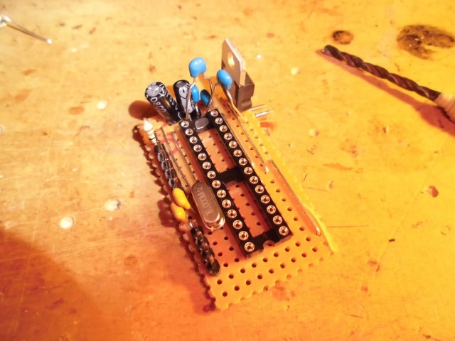
I could’ve left the voltage regulator since it only causes problems. There isn’t even a reason for it since the device will be USB-powered and USB has relatively exact 5 Volts so why care… anyway, I didn’t want to desolder it… yet.
The USB interfacing is done via one of my all time favourite hacks. I once bought about 15 ultra-cheap USB-to-MIDI convertors (~6€ each) and I use one everytime I need USB-Midi in one of my Projects. (Those where you only have a cable with USB on the one and two MIDI conectors on the other side. In between is a circuit taking care of all the USB stuff etc.)
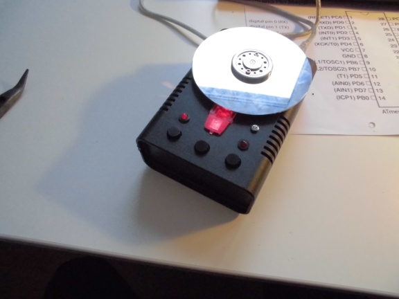
While doing the finetuning I tried different approaches for the coating of the platter. An untreated harddisk platter’s motion will not be recognized by the optical sensor so you have to attach some kind of structure to it.
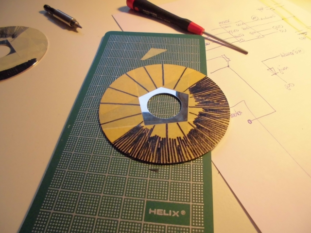
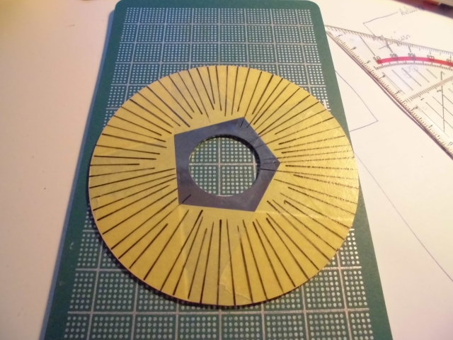
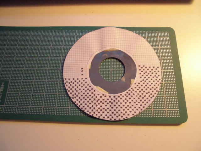
Using plain simple duct tape I was able to yield the best results. The rest will be handled in code.
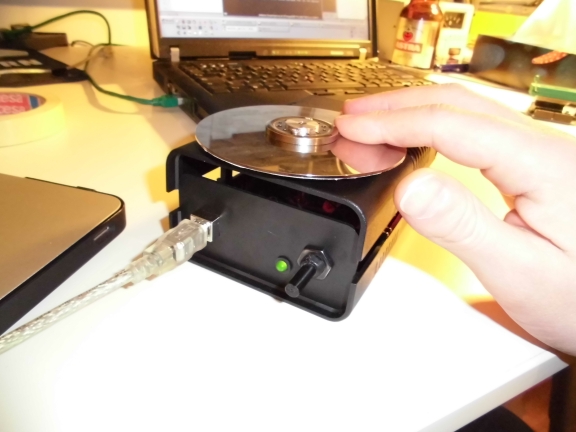
And just as a little side gimmick i added a green led which is lit …
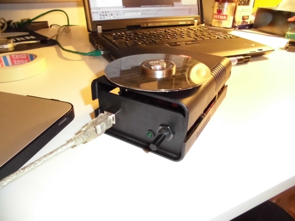
…when you touch the platter. Oh – and it sends out MIDI by the way =) The poti is there to adjust the sensitivity of the touch sensor.
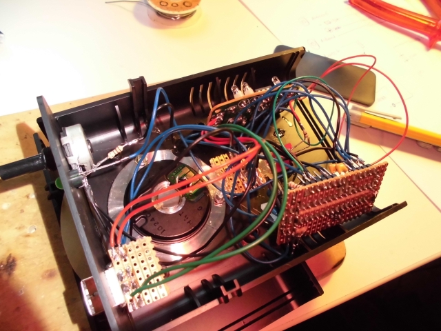
This picture shows the distance between the platter and the optical sensor. I tried different configurations but it turns out that my initial approach was just about perfect.
While thinking about how to actually use this thing I came across a few ideas and added a little more stuff to the circuit
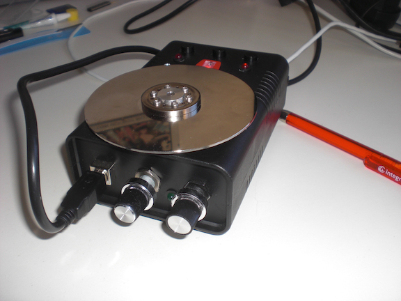
Pressing the left putton will light up the left LED and make the device put out Midi CC #42 when the platter is spun. When the right button is pressed the other LED will light up and Midi CC #43 will be sent upon moving the platter. When the middle button is pressed the Midi Channel will change from 9 to 10 so you can use it for temporary pitchbending, etc. The screw above the LED on the right side is electrically connected to the platter so you have another ‘platter is touched’ contact.
The whole device came out pretty well. I still have some minor quirks when spinning the platter ~really~ fast but I will give it a test run within the next days before altering the code any further.
[Update 10.11.2013]
I added another poti which makes it possible to change the response rate of the platter (and, of course, I altered the micro controller’s code…). That way you don’t have to fiddle around within software but can easily adjust it on the fly
As a result I found a quite easy to do live video scratching within my favorite VJ-software (VDMX)
